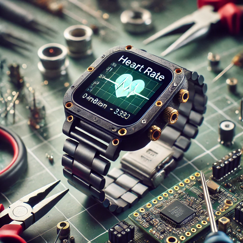
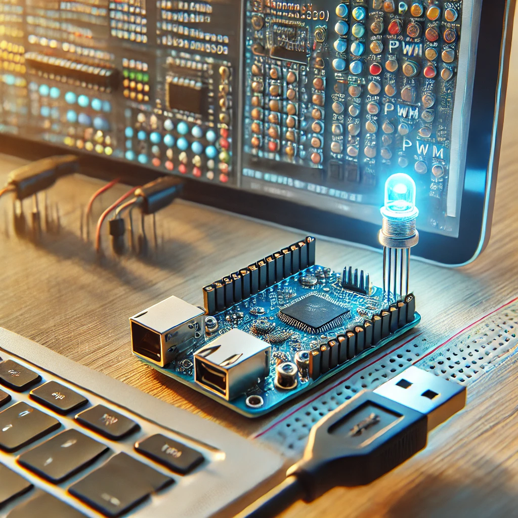
Wearable technology has transformed the way we interact with the world, with smartwatches being one of the most popular gadgets today. A key feature of these devices is their ability to monitor environmental factors and physiological data, enhancing user experience and functionality. Among the various components in a smartwatch, integrating ambient light sensing and heart rate monitoring can make the device smarter, more responsive, and highly personalized.
In this guide, we’ll explore how to design a smartwatch using the ESP32 microcontroller, focusing on two key sensors: an ambient light sensor for automatic screen brightness adjustment and a heart rate sensor for health tracking. We’ll take you through the setup, wiring, coding, and testing phases of this DIY project. By the end, you’ll have a fully functional smartwatch that can adjust to the environment and monitor your health metrics in real-time.
Understanding the ESP32
The ESP32 is a versatile and powerful microcontroller that combines Wi-Fi and Bluetooth capabilities, making it ideal for a wide range of IoT (Internet of Things) applications, including wearable devices. The ESP32 is known for its low power consumption, which is crucial in wearable projects where battery life is a primary concern.
Why ESP32 for a Smartwatch?
- Processing Power: The ESP32 has a dual-core processor, enabling it to handle multiple tasks simultaneously, such as reading sensor data, processing it, and updating the display in real-time.
- Wireless Capabilities: Built-in Wi-Fi and Bluetooth support make it easy to pair the smartwatch with a smartphone or cloud-based services, opening up possibilities for further functionality like remote data syncing.
- Low Power Consumption: Wearables require energy efficiency, and the ESP32’s ability to enter deep sleep mode helps extend battery life.
- GPIO Pins: The ESP32 offers enough GPIO pins to connect various sensors and peripherals like the ambient light and heart rate sensors, and a small display.
Key Components Needed
To bring this smartwatch project to life, you’ll need a few key components. Here’s a breakdown:
- ESP32 Microcontroller: Acts as the main processor for reading sensors and controlling the display.
- Ambient Light Sensor: A sensor like the TSL2561 or BH1750 can detect light levels in the environment, adjusting the display’s brightness accordingly.
- Heart Rate Sensor: The MAX30100 or MAX30102 heart rate sensor uses infrared light to measure the pulse rate through the skin, providing real-time health data.
- OLED Display: A compact and low-power OLED screen (e.g., 0.96-inch I2C OLED) is ideal for displaying data like the ambient light reading and heart rate.
- Battery: A LiPo battery (typically 3.7V) is commonly used in wearable devices due to its compact size and rechargeable nature.
- Charging Circuit: A charging module like the TP4056 is used to safely charge the LiPo battery.
- Wires and Connectors: Various jumper wires, resistors, and connectors for wiring the sensors to the ESP32.
Setting Up the Development Environment
Before starting the hardware setup, you need to prepare your development environment. This includes installing the necessary software and configuring the ESP32.
1. Install Arduino IDE
To program the ESP32, you’ll need the Arduino IDE. If you haven’t already, download and install the latest version of the Arduino IDE from the official website.
2. Add ESP32 Board to Arduino IDE
- Open the Arduino IDE and go to File > Preferences.
- In the “Additional Boards Manager URLs” field, enter the following URL:
https://dl.espressif.com/dl/package_esp32_index.json - Then, navigate to Tools > Board > Board Manager, search for ESP32, and click Install.
3. Install Necessary Libraries
For the ambient light and heart rate sensors, you’ll need to install the corresponding libraries.
- For the Ambient Light Sensor (TSL2561), install the Adafruit TSL2561 library through the Arduino IDE’s Library Manager.
- For the Heart Rate Sensor (MAX30100), install the MAX30100 or SparkFun MAX3010x library.
4. Set Up the ESP32
Connect your ESP32 to your computer using a USB cable. Ensure you select the correct board model and COM port under Tools in the Arduino IDE.
Integrating the Ambient Light Sensor
Wiring the Ambient Light Sensor
The ambient light sensor typically communicates with the ESP32 via I2C protocol, which requires connecting the SCL (clock) and SDA (data) pins. For example:
- SDA to GPIO21 on the ESP32
- SCL to GPIO22
- VCC to 3.3V and GND to ground
Programming the ESP32 to Read Light Data
Here’s a basic code snippet to read data from the ambient light sensor:
Processing Light Data
The lux value from the sensor can be used to adjust the display’s brightness or trigger certain actions in the smartwatch, like dimming the screen in low light conditions.
Integrating the Heart Rate Sensor
Wiring the Heart Rate Sensor
The MAX30100 heart rate sensor works with I2C and has the following connections:
- SDA to GPIO21 on the ESP32
- SCL to GPIO22
- VCC to 3.3V and GND to ground
Programming the ESP32 to Read Heart Rate
Here’s a simple example to read heart rate data from the sensor:
Processing Heart Rate Data
The heart rate data can be displayed on the smartwatch screen, allowing the user to monitor their pulse in real-time.
Designing the Smartwatch UI
The smartwatch UI is crucial for presenting the data in a user-friendly format. You can display both the ambient light and heart rate readings on the OLED display. Use clear, simple text and graphical elements to make the data easily accessible. For instance:
- Display the current light level and heart rate in large, readable fonts.
- Use simple icons or bars to represent the sensor readings.
- Add a sleep mode or dimmed display when ambient light levels drop below a certain threshold.
Power Management for Wearable Devices
Since smartwatches run on batteries, effective power management is essential. The ESP32’s deep sleep mode allows it to conserve power when not actively processing data, which extends battery life. Additionally, the OLED display consumes very little power, making it ideal for wearables.
- Battery Choice: A LiPo battery offers a good balance of size and capacity. Choose one with a suitable capacity (typically 500mAh to 1000mAh) to ensure a decent battery life.
- Charging Circuit: The TP4056 is a popular charging module for LiPo batteries. It ensures safe charging and avoids overcharging.
Testing and Debugging
Once the hardware and software are set up, it’s time to test your smartwatch. Start by checking if the sensor readings are accurate:
- Ambient Light: Ensure that the lux readings change based on the light conditions in your environment.
- Heart Rate: Check the heart rate sensor for consistency, ensuring that it responds to your pulse.
Common issues include:
- Sensor Not Detected: Ensure all wiring is correct and the libraries are installed.
- Inaccurate Readings: Check for noise in the sensor data and adjust the filtering logic as needed.
By following this guide, you can create a basic yet functional smartwatch using the ESP32. The integration of ambient light and heart rate sensors adds valuable features that enhance the usability of the device, making it more responsive to the environment and useful for health monitoring.
You can further expand on this project by adding additional sensors, improving the display’s design, or integrating Bluetooth functionality for smartphone notifications. The possibilities for customization are endless—happy building!
Visit our other website: aibrainpowered.com

