With the rise of smart home technologies, controlling electrical devices remotely has become a staple in modern home automation. One of the key devices enabling this functionality is the ESP32 relay module. Leveraging the power of the ESP32 microcontroller, the relay module provides a simple yet effective way to automate household appliances like lights, fans, and other devices by switching high-voltage AC circuits with a low-voltage digital signal. In this guide, we will take an in-depth look at how to set up the ESP32 relay module to control AC appliances efficiently and explore how you can incorporate it into your home automation system.
What is the ESP32 Relay Module?
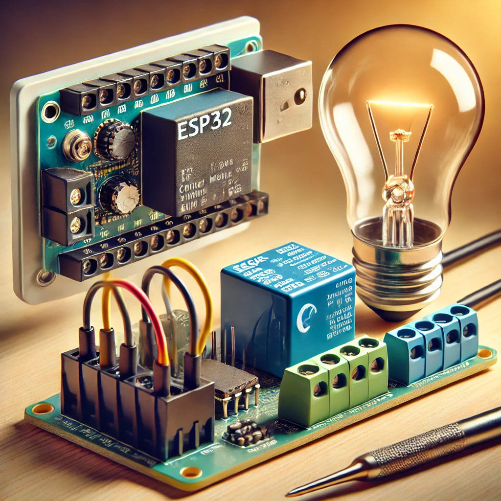
The ESP32 relay module is a combination of a relay and a microcontroller interface. The relay itself is an electromagnetic switch that can control high-voltage devices. The ESP32 microcontroller, known for its low cost, high processing power, and built-in Wi-Fi and Bluetooth, provides the control signal necessary to activate the relay.
- Relay Basics: A relay has a coil that, when energized by a low voltage signal, creates a magnetic field that pulls or releases a switch mechanism. This switch either opens or closes the contacts, which controls the flow of electricity to an external circuit—allowing or cutting off power to an appliance.
- ESP32 Functionality: The ESP32 acts as the brain of the system. It sends out a control signal to the relay to either turn it on or off, thereby controlling connected appliances like lights, fans, or even more complex home systems.
The ESP32 relay module can come in various configurations, including 1-channel, 2-channel, 4-channel, and even 8-channel versions, making it adaptable to different automation needs.
How Does the ESP32 Relay Module Work?
The operation of the ESP32 relay module is based on the principle of switching an AC appliance with a low voltage control signal. Here’s how the system works:
- Relay Mechanism: The relay module consists of a low-voltage input circuit controlled by the ESP32 and a high-voltage output circuit that controls the connected appliances. The input side is where the ESP32 connects to the relay.
- Activation Signal: When the ESP32 sends a high voltage signal (usually 3.3V) to the relay’s input pin, it energizes the relay coil. This action causes the relay to change its state—either closing or opening the contacts, depending on the type of relay.
- Appliance Control: The connected appliance’s circuit is controlled via the relay’s output. In the case of a Normally Open (NO) relay, the circuit will remain open until the relay is activated. Once activated, the contacts close, allowing current to flow and powering the appliance. Conversely, a Normally Closed (NC) relay will allow current to flow when deactivated and stop the current when the relay is triggered.
Materials Needed to Set Up ESP32 Relay Module
Before proceeding with the setup, ensure you have the following materials on hand:
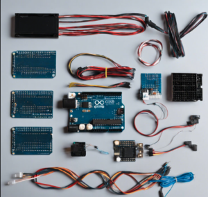
- ESP32 Development Board: This microcontroller comes with built-in Wi-Fi and Bluetooth support, which makes it perfect for IoT projects.
- Relay Module: Choose a relay module based on the number of appliances you want to control. A single-channel relay is suitable for one device, while a multi-channel relay can control several devices.
- Jumper Wires: These are used to connect the ESP32 to the relay module.
- Breadboard (Optional): Useful for organizing connections and prototyping.
- AC Appliances: These are the devices you wish to control (e.g., lamps, fans, etc.).
- External Power Supply: The ESP32 operates on 5V power, so an external power source will be required if not powered via USB.
- Arduino IDE: This is the development environment used to write and upload code to the ESP32.
Wiring the ESP32 Relay Module
Before you can begin writing code or testing the system, it’s essential to wire the ESP32 development board to the relay module correctly. Follow these steps to connect the components:
-
Relay Module Pins:
- VCC Pin: Connect this pin to the 5V output of the ESP32. It provides the necessary power for the relay module.
- GND Pin: Connect the ground (GND) pin of the relay to the GND pin of the ESP32.
- IN1 Pin: Connect the relay’s input pin to any available GPIO pin of the ESP32 (e.g., GPIO 13 or GPIO 12). This pin will receive the control signal from the ESP32 to activate the relay.
-
Connecting the AC Appliance:
- COM Pin: This is the “Common” pin, which should be connected to the live wire (or “hot” wire) of your AC appliance.
- NO Pin (Normally Open): The output pin should be connected to the live wire leading to the appliance. When the relay is activated, the circuit will be completed, and the appliance will receive power.
- NC Pin (Normally Closed): Alternatively, you can use the NC pin if you want the appliance to be off by default. When the relay is activated, the current will stop, and the appliance will be turned off.
-
Powering the System: Make sure the ESP32 is powered through USB or an external power source. The relay module typically operates at 5V, so ensure your power supply is adequate for the ESP32 and relay module.
ESP32 Relay Control Code
Once the wiring is complete, the next step is to program the ESP32 to control the relay and the connected AC appliances. Using the Arduino IDE, you can write a simple program to switch the relay on and off.
Here’s an example of code to control a single-channel relay:
Integrating with Wi-Fi for Remote Control
One of the primary advantages of the ESP32 is its built-in Wi-Fi. With Wi-Fi functionality, you can control the ESP32 relay module remotely, allowing you to turn appliances on or off from your smartphone or other devices.
Here’s how to integrate the ESP32 with Wi-Fi and create a simple web interface for controlling the relay remotely:
This code sets up an HTTP server that serves a webpage with buttons to control the relay. You can access the web interface from any device on the same network to control your appliance remotely.
Safety Precautions
Working with high-voltage AC appliances requires caution. Here are some essential safety guidelines to follow:
- Proper Insulation: Ensure all wires are properly insulated, especially when working with high-voltage connections.
- Fuse and Circuit Breaker: Always use fuses or circuit breakers to protect your appliances from electrical overloads.
- Double-Check Connections: Verify all connections are secure and properly insulated before powering up the system.
- Work in a Dry Environment: Avoid working with electronics in damp or wet environments to prevent short circuits or electrical shocks.
Troubleshooting Tips
If you encounter issues with the relay module, consider the following troubleshooting tips:
- Relay Not Triggering: Ensure the GPIO pin is correctly connected and the ESP32 is powered properly. Try using a different GPIO pin to rule out issues.
- Relay Clicking but Appliance Not Turning On: Verify the AC wiring to the appliance and ensure that the relay is wired to the appliance correctly.
- Inconsistent Web Interface Control: Check the Wi-Fi connection. Ensure your ESP32 is connected to the network and has a stable connection.
The ESP32 relay module is a powerful and versatile tool for controlling AC appliances efficiently. With its ability to handle high-voltage devices, it opens up a world of possibilities for smart home automation and IoT projects. By following this guide, you can easily set up the relay module to control appliances remotely and start experimenting with your own home automation projects.
As you gain more experience, you can integrate more advanced features, such as scheduling, voice control, or even integrating your relay system with existing smart home platforms like Home Assistant. With the flexibility and power of the ESP32, the potential for home automation is limitless.
Visit our other website: https://synergypublish.com

