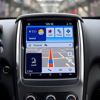
Learn how to build a smart navigation system using ESP32, GPS module, and OLED display. This step-by-step guide covers hardware setup, programming, and testing, perfect for robotics and DIY enthusiasts.
Navigating through unknown environments can be challenging, but with the rise of affordable microcontrollers, building a smart navigation system is now accessible to hobbyists and enthusiasts. The ESP32 is a powerful microcontroller that comes with both Wi-Fi and Bluetooth capabilities, making it perfect for building IoT projects, including smart navigation systems. In this article, we will walk you through building a fully-functional smart navigation system using the ESP32, GPS module, and other essential components.
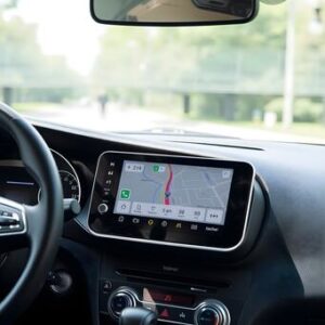
The ESP32 is highly versatile and can easily integrate with various sensors and devices, including GPS modules, displays, and motor controllers. This makes it ideal for applications ranging from car navigation systems to robotics. By following this guide, you will create a navigation system that can track locations, display directions, and even provide real-time feedback, making it suitable for personal use, robotic systems, or vehicles.
Let’s dive into the step-by-step process of setting up this navigation system. We’ll start by introducing the necessary hardware and software components before moving on to the wiring, coding, and testing stages. By the end of this article, you will have a fully operational navigation system ready for real-world use.
Smart Navigation System
The ESP32 is an ideal choice for this project due to its Wi-Fi and Bluetooth capabilities, making it perfect for connecting to external systems and the internet. It provides adequate processing power to handle tasks like GPS tracking, real-time updates, and user interactions. Combined with a GPS module, the ESP32 can help you track your exact position and guide you to your destination using the correct set of coordinates.
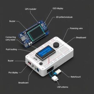
For this project, the ESP32 will work as the brain of the system, processing GPS data, sending commands to motors (if necessary), and displaying information. The GPS module provides location data, including latitude, longitude, altitude, and speed, which can be used to track your movement or guide you to a specific destination. The optional OLED display will show the user’s current coordinates and other relevant data, making it easy to monitor your progress.
The main objective of this navigation system is to offer easy access to essential navigation information like your current location, speed, and the destination you’re navigating toward. By integrating the ESP32 with GPS and an OLED display, you’ll create a compact and efficient system. This system can be useful for a wide range of applications, including personal navigation, vehicle systems, or autonomous robots.
Building a smart navigation system has become increasingly popular, thanks to the versatility of the ESP32. With the necessary components in hand, the project becomes straightforward and accessible to both beginners and advanced users. Once the hardware and software are set up, the system can offer real-time updates, guiding the user to their desired destination with ease.
In addition to its functionality, the ESP32’s low power consumption makes it ideal for portable projects. It can run on a small battery for extended periods, making it suitable for outdoor navigation, hiking, biking, or even integration into mobile robots. Its connectivity options also make it possible to send or receive data remotely, opening the door to more advanced features, such as cloud-based navigation or voice interaction.
While the hardware setup is simple, the software aspect is crucial for ensuring that the navigation system operates smoothly. You’ll need to program the ESP32 to receive GPS data, process it, and display it on the screen. Additionally, the system can be customized with features like voice commands, real-time mapping, or even automatic route generation.
Let’s begin by discussing the hardware components needed for this project, followed by setting up the development environment for programming the ESP32.
Hardware Requirements for the Project
ESP32 Development Board
The heart of the navigation system is the ESP32 development board. The ESP32 is a low-cost, low-power microcontroller with dual-core processors, making it ideal for handling multiple tasks simultaneously. It also supports both Wi-Fi and Bluetooth, which allows it to connect with external devices like smartphones, computers, or even cloud services. You can find various ESP32 development boards in the market, including popular options like the ESP32 DevKit C.
GPS Module (NEO-6M)
The GPS module is a key component of the navigation system, providing real-time location data. The NEO-6M GPS module is a widely used choice in DIY navigation projects. This module can communicate with the ESP32 via serial communication and provides information such as latitude, longitude, altitude, and speed. The GPS module requires a clear view of the sky to work effectively, so it’s important to place it in a location with minimal obstructions.
OLED Display
An OLED display is an optional but valuable addition to your navigation system. It allows you to display the current GPS coordinates, speed, and other relevant information. A small 128×64 pixel OLED screen can be connected to the ESP32, and the information will be updated in real-time. OLED displays are ideal for this project because they are energy-efficient and provide excellent contrast and readability.
Motor Driver and Motors (For Mobile Robots)
If you’re building a mobile navigation system (e.g., a robot), you will need motors and a motor driver. The motor driver will interface with the ESP32 to control the movement of the robot based on the GPS data. The ESP32 will send commands to the motor driver, which will then control the speed and direction of the motors.
Push Buttons
Buttons can be used to interact with the system. For example, they can be used to switch between different modes (e.g., home or destination mode) or reset the system. The ESP32 has plenty of GPIO pins, so you can easily connect push buttons to control the navigation system’s functionality.
Jumper Wires and Breadboard
For connecting the components together, you will need jumper wires and a breadboard. These are essential for building your circuit and prototyping the navigation system. They allow you to make secure and temporary connections between the ESP32, GPS module, OLED display, and other components before creating a more permanent setup.
Power Supply
The ESP32 and the other components will require a power source. For portability, you can use a 5V battery pack or a LiPo battery. This power supply will ensure the system runs smoothly during use, whether it’s on a mobile robot or carried for personal navigation.
Setting Up the ESP32 Development Environment
Before you start coding and assembling the hardware, it’s important to set up the development environment for the ESP32. This process ensures that you can upload your code to the ESP32 and run the project successfully.
Step 1: Install Arduino IDE
The easiest way to program the ESP32 is using the Arduino IDE. Download and install it from the official Arduino website. The IDE supports both Windows and macOS platforms, so choose the correct version for your operating system.
Step 2: Add ESP32 Board to the Arduino IDE
To work with the ESP32 in the Arduino IDE, you need to install the ESP32 board library. Open the Arduino IDE and navigate to File > Preferences. In the “Additional Boards Manager URLs” field, paste the following URL: https://dl.espressif.com/dl/package_esp32_index.json. Then, go to Tools > Board > Boards Manager, search for “ESP32”, and click Install.
Step 3: Select the Correct ESP32 Board
Once the board manager is installed, go to Tools > Board and select the correct ESP32 board from the list. For example, if you’re using the ESP32 DevKit C, choose that specific model. This step ensures that your code is compiled for the correct hardware.
Step 4: Set the Correct Port
Under Tools > Port, select the appropriate COM port for the ESP32. This allows the Arduino IDE to communicate with your board during programming.
Step 5: Install Required Libraries
To use the GPS module and OLED display, you’ll need to install the relevant libraries. Go to Sketch > Include Library > Manage Libraries and search for TinyGPS++. This library will help you interact with the GPS module and extract location data. Similarly, search for Adafruit_SSD1306 and Adafruit_GFX to work with the OLED display.
Step 6: Test the Setup
Before diving into the project, test the setup by uploading a simple example code to the ESP32. This ensures that the board is properly configured and ready for development. You can start with a basic “Hello World” example or test the GPS and OLED modules individually.
Step 7: Start Writing the Code
Now that the environment is set up, you can start writing the code for your ESP32 Smart Navigation System. In the next sections, we will go over how to wire the components and program the ESP32 to handle GPS data, display it, and provide navigation instructions.
Wiring the Components Together
Now that you’ve set up the development environment, let’s wire the components together. Proper connections are crucial to ensure that the system functions as intended.
1. GPS Module to ESP32
The GPS module communicates with the ESP32 through serial communication. Connect the TX pin of the GPS to the RX pin on the ESP32 (GPIO16), and the RX pin of the GPS to the TX pin on the ESP32 (GPIO17). Additionally, connect the VCC pin of the GPS module to the 5V pin on the ESP32 and the GND pin to the GND pin.
2. OLED Display to ESP32
To wire the OLED display, connect the SCL pin of the OLED to GPIO22 and the SDA pin to GPIO21. Connect the VCC pin of the display to the 3V3 pin on the ESP32, and the GND pin to the GND pin.
3. Motor Driver (Optional)
If you’re adding motors for a mobile robot, connect the motor driver’s IN1, IN2, IN3, and IN4 pins to the appropriate GPIO pins on the ESP32. You will also need to connect the motor power supply to the motor driver’s VCC and GND pins.
4. Power Supply
Connect the power supply to the ESP32’s 5V pin and GND. Make sure the voltage and current ratings of the power supply match the needs of the ESP32 and connected components.
Once all the components are connected securely, you can begin writing the code to handle GPS data, display it, and implement the navigation logic.
Programming the ESP32 for Smart Navigation
Now that the hardware is set up, it’s time to start programming the ESP32. We’ll break down the code into key sections.
Step 1: Include Libraries
To communicate with the GPS module and the OLED display, we need to include the necessary libraries.
Step 2: Initialize Components
In the setup() function, initialize the serial communication, the OLED display, and the GPS module.
Step 3: Read GPS Data
In the loop() function, read the GPS data and update the display with the current coordinates.
Step 4: Add Navigation Logic (Optional)
You can expand the code to add more advanced navigation features, such as setting a destination and guiding the user with real-time instructions. For now, this basic setup will display the current GPS coordinates on the OLED screen.
Testing the ESP32 Smart Navigation System
After completing the wiring and programming, it’s time to test the system. Begin by uploading the code to the ESP32 and checking the OLED display for the GPS coordinates. Move the GPS module to an open area to receive GPS signals.
If the system works as expected, you should see your current location displayed on the OLED screen. If you wish to extend the project, you can integrate additional features like motor control or integrate the system with a mobile app.
This project can be expanded in multiple ways. You could add motor control for a mobile robot, integrate a mapping system for more advanced navigation, or even connect the system to a smartphone or cloud service for additional functionality. The possibilities are endless.
By following this guide, you’ve gained hands-on experience with GPS integration, ESP32 programming, and basic navigation system design. Enjoy experimenting with the system and creating new features to make it even smarter!
FAQs
1. Can the ESP32 handle GPS data processing efficiently?
Yes, the ESP32 can efficiently handle GPS data processing thanks to its dual-core processor and ample memory. You can use libraries like TinyGPS++ to simplify data handling. Learn more at www.espressif.com.
2. What GPS module is recommended for this project?
The NEO-6M GPS module is commonly used for its affordability and ease of integration. It connects seamlessly with the ESP32 via UART. For module details, visit www.u-blox.com.
3. How can I improve GPS accuracy?
Improving GPS accuracy involves using a high-quality antenna, positioning the module in an open area, and enabling DGPS (Differential GPS). Learn more about GPS accuracy at www.gps.gov.
4. Do I need an external power source for the ESP32?
While the ESP32 can be powered via USB, it’s better to use a reliable external power source for outdoor projects. Check out power options at www.adafruit.com.
5. Is the OLED display necessary for the navigation system?
While not mandatory, an OLED display provides real-time visual feedback, making navigation more user-friendly. For OLED displays, visit www.sparkfun.com.
6. Can I use a different display type instead of OLED?
Yes, you can use alternatives like TFT LCD or ePaper displays. These options may require different libraries and configurations. Learn more at www.waveshare.com.
7. How can I add voice navigation to the system?
You can integrate text-to-speech libraries or connect the ESP32 to a Bluetooth speaker for voice guidance. Tutorials can be found at www.instructables.com.
8. What are the benefits of using Wi-Fi in this navigation system?
Wi-Fi enables additional features like location sharing, cloud integration, or fetching map data from online sources. For Wi-Fi tips, visit www.arduino.cc.
9. Can this navigation system be used for vehicles?
Yes, the system can be adapted for vehicles by integrating OBD-II data for enhanced features. Explore OBD-II integration at www.obdlink.com.
10. Are there any legal restrictions for using GPS modules?
In some regions, GPS modules might have restrictions regarding civilian accuracy or usage. Check your local regulations at www.fcc.gov.
Did you find this helpful? If you did, please share and stay tuned to our blog!!

