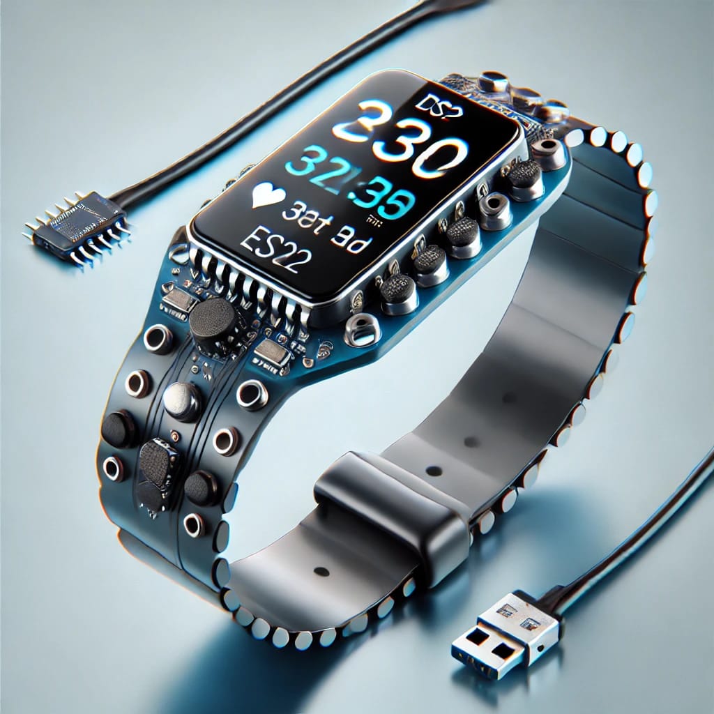
Wearable fitness trackers have revolutionized personal health monitoring, making it easier to track physical activities, heart rate, and overall fitness goals. This guide provides a detailed step-by-step approach to creating a wearable fitness tracker using the ESP32, starting from component selection to programming and final assembly.
Why Build Your Own Fitness Tracker?
Building your own fitness tracker offers several advantages: cost savings, customization, and a deeper understanding of wearable technology. While commercial fitness trackers come preloaded with specific features, a DIY tracker allows you to design one tailored to your specific needs. You can choose which features to include, such as heart rate monitoring, step tracking, or even integration with your smart home.
Additionally, the ESP32 microcontroller is ideal for wearable projects because of its compact design, Bluetooth and Wi-Fi capabilities, and energy efficiency. Unlike other development boards, the ESP32 can easily interface with a variety of sensors and displays, making it a versatile choice.
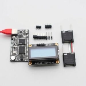
Components Required
To create your fitness tracker, you’ll need the following components:
- ESP32 Dev Board: The “brain” of your tracker, responsible for managing sensors and connectivity.
- Heart Rate Sensor (MAX30102): Measures heart rate and blood oxygen levels.
- Accelerometer (MPU6050): Tracks movement and steps, and analyzes activity levels.
- OLED Display (0.96-inch): Shows real-time data like steps, heart rate, and time.
- LiPo Battery (1000mAh): Powers the ESP32 and connected components.
- TP4056 Battery Management Module: Ensures safe charging and power regulation.
- Jumper Wires: For prototyping and connecting components.
- 3D-Printed Enclosure: Protects the components and ensures the device is wearable.
Setting Up Your Development Environment
Before assembling the hardware, prepare your ESP32 for programming.
Step 1: Install Arduino IDE
Download and install the Arduino IDE from www.arduino.cc. Once installed, open the IDE and navigate to File > Preferences. Add the following URL to the Additional Board Manager URLs:
https://dl.espressif.com/dl/package_esp32_index.json.
Step 2: Install ESP32 Board Support
Go to Tools > Board > Boards Manager, search for “ESP32,” and click install. This will enable the Arduino IDE to recognize your ESP32 dev board.
Step 3: Install Required Libraries
Install the libraries for your sensors and display. In the Arduino IDE, go to Sketch > Include Library > Manage Libraries, and search for:
- Adafruit MAX30102 (heart rate sensor)
- Adafruit MPU6050 (accelerometer)
- Adafruit SSD1306 (OLED display)
Install each library to simplify coding and interfacing with components.
Step 4: Test the Setup
Connect the ESP32 to your computer using a USB cable, select the appropriate board and COM port under the Tools menu, and upload a test sketch like “Blink” to ensure the ESP32 is communicating with your computer.
Wiring the Components
Proper wiring ensures the functionality of the fitness tracker. Below is a detailed guide for connecting each component.
Heart Rate Sensor (MAX30102)
- SCL Pin: Connect to GPIO 22 on the ESP32.
- SDA Pin: Connect to GPIO 21.
- VCC: Connect to the 3.3V pin of the ESP32.
- GND: Connect to GND on the ESP32.
Accelerometer (MPU6050)
- SCL Pin: Connect to the same GPIO 22.
- SDA Pin: Connect to GPIO 21.
- VCC: Connect to the 3.3V pin of the ESP32.
- GND: Connect to GND.
OLED Display
- SCL Pin: Connect to GPIO 22 (shared with the sensors).
- SDA Pin: Connect to GPIO 21.
- VCC: Connect to 3.3V.
- GND: Connect to GND.
Power Management Module
Connect the LiPo battery to the BAT IN terminals of the TP4056 module. Use the module’s output to power the ESP32 through the VIN and GND pins.
Programming the ESP32
Step 1: Initialize Sensors
In the Arduino IDE, write code to initialize the heart rate sensor, accelerometer, and OLED display. Use the libraries installed earlier for quick setup. For example:
Step 2: Add Data Processing
Add functions to process data from the sensors. For example, calculate heart rate averages or step counts based on accelerometer data.
Step 3: Display Data
Use the SSD1306 library to send data to the OLED display. For example:
Upload the program to the ESP32 and verify functionality.
Assembly and Final Touches
After programming and testing the ESP32 fitness tracker, the next step is assembling the components into a wearable form. This stage requires careful handling to ensure the durability and usability of the tracker. Below is a detailed guide to assembling the device and adding the finishing touches.
Securing the ESP32 and Sensors
- Mounting the ESP32:
- Position the ESP32 securely inside the 3D-printed enclosure. Use screws, adhesive pads, or brackets to keep the board in place. Ensure that the USB port remains accessible for charging or reprogramming purposes.
- Positioning the Sensors:
- Attach the heart rate sensor (MAX30102) to a location that will maintain consistent contact with the skin, such as the back of the enclosure. Use double-sided adhesive tape or small screws for mounting. Ensure the sensor has clear access to the skin for accurate readings.
- Place the accelerometer (MPU6050) inside the enclosure in a stable position. Align it properly to avoid miscalculations in movement tracking.
- Mounting the OLED Display:
- Position the OLED display on the top surface of the enclosure for easy visibility. Secure it with adhesive pads or screws. Be careful not to damage the delicate ribbon cable connecting the display to the ESP32.
Managing Power Connections
- Attaching the Battery:
- Secure the LiPo battery inside the enclosure using adhesive tape or a dedicated slot in the 3D-printed case. The battery should be positioned in a way that does not obstruct the components or wiring.
- Connect the battery to the TP4056 module, ensuring the connections are tight and secure to prevent disconnection during use.
- Power Routing:
- Use short, neatly arranged wires to connect the TP4056 module to the ESP32. Ensure that the positive and negative terminals are correctly matched to prevent damage.
Cable Management
- Routing Wires:
- Organize all wires inside the enclosure using cable ties or adhesive clips. This reduces clutter and minimizes the risk of wires getting pinched or damaged.
- Use heat shrink tubing on exposed connections to improve durability and safety.
- Testing Connections:
- Before sealing the case, double-check all connections to ensure proper functionality. Test the heart rate sensor, accelerometer, and OLED display to confirm they are working as intended.
Final Enclosure Assembly
- Sealing the Enclosure:
- Once all components are securely mounted and tested, close the 3D-printed case using screws or snap-fit mechanisms. Ensure the case is tight enough to protect the internal components but not so tight that it damages them.
- Creating Access Points:
- If your case design allows, include cutouts for accessing the USB port or a power switch. This makes it convenient to charge the device or turn it on/off without opening the enclosure.
- Adding Straps or Clips:
- Attach straps, bands, or clips to the case to make the tracker wearable. For wrist-mounted designs, consider using elastic or Velcro straps for comfort and adjustability.
Usability Testing
- Comfort Check:
- Wear the assembled fitness tracker to ensure it sits comfortably on the wrist or arm. Adjust the strap or band as needed to provide a snug but not restrictive fit.
- Functionality Test:
- Verify that the device operates as expected in real-world conditions. Check the display, heart rate readings, and step tracking. Test it during various activities, such as walking, running, or sitting, to evaluate its accuracy and responsiveness.
- Durability Assessment:
- Test the robustness of the enclosure and components by wearing the device during normal activities. Ensure that all parts remain securely attached and that the wiring remains intact.
Aesthetic and Final Touches
- Personalizing the Tracker:
- Paint or decorate the enclosure to match your style. Use durable, non-toxic paints or vinyl wraps to add a professional finish.
- Labeling Buttons or Ports:
- Use stickers or permanent markers to label buttons, switches, or ports for ease of use. This is especially helpful if others will use the device.
- Adding a Companion App (Optional):
- Enhance the functionality of the fitness tracker by pairing it with a smartphone app. Apps like Blynk can display detailed statistics, enable remote control, and even log long-term data.
By following these detailed assembly steps, you’ll have a robust and functional ESP32 fitness tracker that is not only efficient but also comfortable and stylish to wear.
Frequently Asked Questions (FAQs)
1. What are the benefits of using ESP32 for a fitness tracker?
The ESP32 is an ideal choice for fitness trackers because it offers built-in Wi-Fi and Bluetooth connectivity, allowing seamless communication with mobile devices or cloud platforms. It also supports multiple GPIO pins, which can connect to sensors like heart rate monitors and accelerometers. Additionally, its low-power consumption mode ensures that the tracker has a long battery life.
For more details on ESP32 features, visit https://www.espressif.com.
2. Can I integrate additional features like GPS or temperature monitoring?
Yes, you can expand the capabilities of your ESP32 fitness tracker by integrating modules like GPS for location tracking or temperature sensors to monitor body temperature. Ensure your enclosure has sufficient space to accommodate these additional components, and update the software to handle the new data inputs.
Learn more about compatible modules at https://www.adafruit.com.
3. What is the typical battery life of an ESP32 fitness tracker?
Battery life depends on the type of battery used, the sensors, and the usage pattern. A standard 1000mAh LiPo battery can power a fitness tracker for approximately 1-3 days under typical usage conditions. Enabling deep sleep mode on the ESP32 significantly increases battery life.
Explore power optimization techniques at https://www.sparkfun.com.
4. How accurate are the heart rate and step tracking features?
The accuracy of the heart rate sensor depends on the quality of the sensor (e.g., MAX30102 is highly reliable) and how securely it fits against the skin. Step tracking accuracy relies on the calibration of the accelerometer and the algorithm used to process motion data. Fine-tuning these parameters can improve results.
Check sensor reviews at https://www.seeedstudio.com.
5. Can I connect my fitness tracker to a mobile app?
Yes, your ESP32 fitness tracker can communicate with mobile apps via Bluetooth or Wi-Fi. Apps like Blynk or custom-built apps using platforms like MIT App Inventor can display real-time data and provide an interface for configuration.
Get started with Blynk at https://www.blynk.io.
6. What programming languages are used for ESP32 fitness trackers?
The ESP32 is primarily programmed using C or C++ via the Arduino IDE or ESP-IDF (Espressif IoT Development Framework). Python (MicroPython) can also be used for simpler applications. Arduino is generally preferred for beginners due to its user-friendly environment.
Learn Arduino basics at https://www.arduino.cc.
7. What kind of display can I use with the ESP32 fitness tracker?
OLED displays, such as the SSD1306, are commonly used due to their compact size, low power consumption, and clarity. These displays can show data like time, steps, and heart rate, and are easy to interface with the ESP32 using I2C communication.
Find OLED displays at https://www.digikey.com.
8. Can I use a rechargeable battery, and how do I charge it?
Yes, a rechargeable LiPo battery is recommended. Charging can be achieved using a TP4056 charging module, which safely regulates the charging process. The module can be connected to a USB port for convenient recharging.
Read about safe charging practices at https://www.allaboutcircuits.com.
9. What happens if one of the sensors stops working?
If a sensor stops working, first check the connections and power supply. Replace damaged wires or reconnect loose connections. If the issue persists, test the sensor on a separate circuit to confirm if it’s faulty. Replace it if necessary.
Troubleshooting tips are available at https://www.electronics-tutorials.ws.
10. How can I make my fitness tracker waterproof?
To make your fitness tracker waterproof, you can use a silicone sealant around the enclosure seams and buttons. Ensure the sensors that need skin contact, such as heart rate monitors, are exposed but protected by waterproof membranes. Use a waterproof 3D-printed case for added durability.
Explore waterproofing materials at https://www.mouser.com.
These FAQs provide detailed insights into setting up and enhancing your ESP32 fitness tracker, ensuring a smooth and reliable experience for both beginners and advanced users.
Did you find this helpful? If you did, please stay tuned to our blogs!!
Feel free to visit for all the know-how for 3D printing https://master3dp.com/

