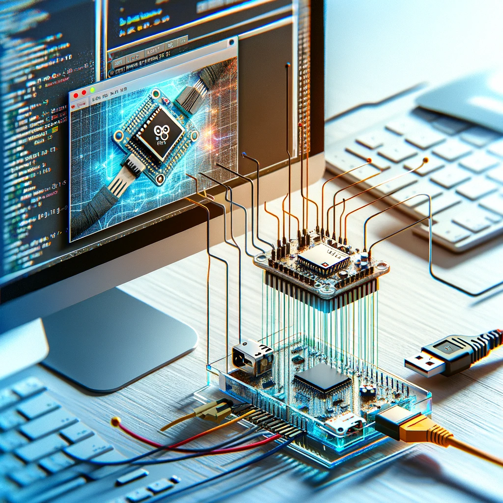
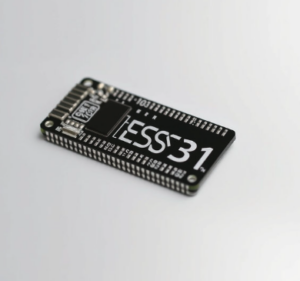
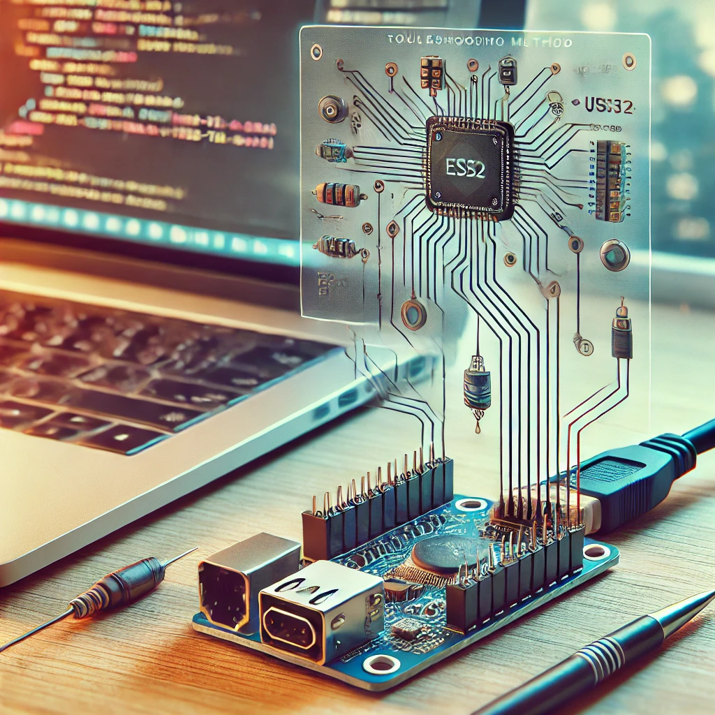
The ESP32-CAM module is a versatile and cost-effective solution for embedding camera functionality in IoT and hobbyist projects. Its powerful features, including built-in Wi-Fi and Bluetooth, make it ideal for applications like video streaming, image processing, and smart surveillance systems. This guide provides step-by-step instructions to help beginners set up, program, and troubleshoot their ESP32-CAM projects with ease.
Introduction
The ESP32-CAM is a popular microcontroller module with an integrated camera. Whether you are building a home security system, an AI-powered face recognition tool, or simply experimenting with IoT devices, this compact module offers an affordable entry point. This guide is designed to simplify the process for beginners, detailing every step from setup to testing and troubleshooting.
What You Will Learn
-
The advantages of using the ESP32-CAM.
-
The tools and components required for setup.
-
How to configure the development environment.
-
How to program and test the ESP32-CAM.
-
Tips for troubleshooting common issues.
By the end of this guide, you will have a fully functional ESP32-CAM module running your desired project.
Why Choose ESP32-CAM?
The ESP32-CAM stands out in the market due to its impressive combination of features and affordability. Below are the reasons why it is an excellent choice for your projects:
Key Features
-
Low Cost: Priced affordably, it is accessible to hobbyists and students alike.
-
Compact Design: The small form factor makes it suitable for projects where space is limited.
-
Built-in Camera: Includes an OV2640 camera module capable of capturing high-quality images and streaming videos.
-
Powerful Processor: The dual-core ESP32 chip supports advanced applications, including machine learning and image processing.
-
Wireless Connectivity: Integrated Wi-Fi and Bluetooth functionality for seamless communication.
Popular Applications
-
Home surveillance and security systems.
-
Motion detection and face recognition.
-
Live video streaming for IoT devices.
-
Smart agriculture systems for remote monitoring.
-
Educational and DIY electronics projects.
Tools and Components Required
Before starting, ensure you have the necessary hardware and software tools. Here’s a checklist:
Hardware
-
ESP32-CAM Module: The main microcontroller with a camera.
-
FTDI Adapter: For connecting the ESP32-CAM to your computer via USB. Ensure it supports 3.3V.
-
Jumper Wires: For making secure connections between the ESP32-CAM and the FTDI adapter.
-
USB Cable: To connect the FTDI adapter to your computer.
-
Breadboard (Optional): Useful for organizing connections during testing.
Software
-
Arduino IDE: A user-friendly development environment for writing and uploading code.
-
ESP32 Board Package: Adds support for ESP32-based boards within the Arduino IDE.
-
CameraWebServer Example Code: A pre-configured sketch to test the ESP32-CAM’s camera functionality.
By gathering these tools, you’ll ensure a smooth setup process without interruptions.
Setting Up the Environment
Configuring the development environment is a crucial step to get the ESP32-CAM working. Follow these steps to prepare your system.
Step 1: Install Arduino IDE
-
Visit the official Arduino website.
-
Download the appropriate version for your operating system (Windows, macOS, or Linux).
-
Install the IDE by following the on-screen instructions.
-
Open the Arduino IDE to ensure it launches correctly.
Step 2: Install the ESP32 Board Package
-
Open the Arduino IDE and navigate to File > Preferences.
-
In the “Additional Board Manager URLs” field, add the following URL:
https://dl.espressif.com/dl/package_esp32_index.json -
Go to Tools > Board > Board Manager, and search for “ESP32”.
-
Install the package by Espressif Systems.
This step ensures that your Arduino IDE recognizes the ESP32-CAM module.
Connecting ESP32-CAM to Your Computer
The ESP32-CAM does not have a built-in USB interface, requiring an FTDI adapter for programming. Proper wiring is essential for a successful connection.
Step 1: Wiring the ESP32-CAM and FTDI Adapter
-
Connect the Pins: Use jumper wires to make the following connections:
-
ESP32-CAM GND to FTDI GND
-
ESP32-CAM 3.3V to FTDI VCC (3.3V)
-
ESP32-CAM U0R to FTDI TX
-
ESP32-CAM U0T to FTDI RX
-
ESP32-CAM IO0 to GND (for programming mode)
-
-
Set the FTDI Adapter to 3.3V: Most adapters have a switch to toggle between 3.3V and 5V. Ensure it is set to 3.3V to avoid damaging the ESP32-CAM.
Step 2: Connect to the Computer
-
Plug the FTDI adapter into your computer using the USB cable.
-
Verify that the device is recognized by your system.
Programming the ESP32-CAM
Programming the ESP32-CAM involves loading code through the Arduino IDE. The following steps detail the process.
Step 1: Select the Correct Board
-
In the Arduino IDE, go to Tools > Board > ESP32 Arduino, and select “AI Thinker ESP32-CAM”.
-
Configure the additional settings:
-
Flash Frequency: 40 MHz
-
Partition Scheme: Huge APP (3MB No OTA)
-
Step 2: Load the CameraWebServer Example
-
Navigate to File > Examples > ESP32 > Camera > CameraWebServer.
-
Replace the default Wi-Fi credentials in the code with your network’s SSID and password:
const char* ssid = "Your_SSID"; const char* password = "Your_PASSWORD"; -
Ensure the correct camera model is selected in the code. For most ESP32-CAM modules, use:
#define CAMERA_MODEL_AI_THINKER
Step 3: Upload the Code
-
Press the “Upload” button in the Arduino IDE.
-
While the code is uploading, ensure the IO0 pin remains connected to GND.
-
After the upload is complete, disconnect the IO0 pin from GND and press the reset (RST) button on the ESP32-CAM.
Testing the ESP32-CAM
After uploading the code, test the ESP32-CAM to ensure it is functioning correctly.
Step 1: Access the Serial Monitor
-
Open the Serial Monitor in the Arduino IDE (Tools > Serial Monitor).
-
Set the baud rate to 115200.
-
Observe the output for the IP address assigned to the ESP32-CAM by your Wi-Fi network.
Step 2: Open the Camera Interface
-
Copy the IP address from the Serial Monitor.
-
Open a web browser and paste the IP address into the address bar.
-
You should see the CameraWebServer interface, allowing you to capture images, stream video, and adjust camera settings.
Troubleshooting Tips
Even with detailed instructions, you may encounter issues. Below are common problems and their solutions:
Problem 1: Compilation Errors
-
Solution: Ensure the ESP32 board package is correctly installed and the correct board is selected in the Arduino IDE.
Problem 2: No Serial Output
-
Solution: Verify the wiring between the ESP32-CAM and the FTDI adapter. Check that the IO0 pin is connected to GND during programming.
Problem 3: Camera Initialization Failed
-
Solution:
-
Ensure the camera module is securely connected to the ESP32-CAM.
-
Verify that the correct camera model is selected in the code.
-
Problem 4: Cannot Access Web Interface
-
Solution:
-
Check the Wi-Fi credentials entered in the code.
-
Ensure the ESP32-CAM is within range of the Wi-Fi network.
-
Frequently Asked Questions (FAQ)
Can the ESP32-CAM Work Without an FTDI Adapter?
Yes, after programming, the ESP32-CAM can run standalone by providing power through its 3.3V and GND pins.
What Is the Maximum Camera Resolution?
The ESP32-CAM’s OV2640 camera supports resolutions up to 1600×1200 pixels (UXGA).
How Do I Reset the ESP32-CAM?
Press the RST button on the module to perform a reset.
The ESP32-CAM is a powerful and affordable tool for integrating camera functionality into IoT projects. With its compact design, versatile features, and simple setup process, it is an excellent choice for hobbyists and professionals alike. By following this guide, you have successfully set up and programmed your ESP32-CAM module, unlocking endless possibilities for innovative projects.
Visit our other website: machinepwr.com

