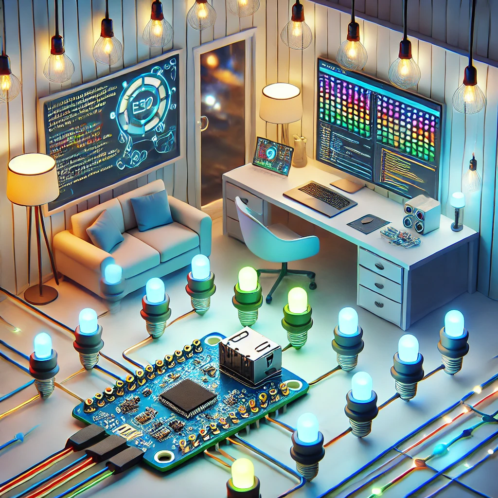
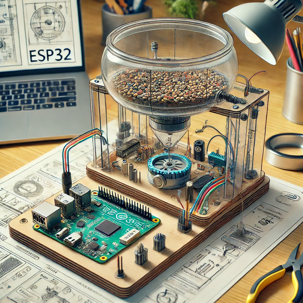
Learn how to turn your ESP32 into a smart lighting solution. This step-by-step guide covers setup, coding, and testing, making your lights smarter and more efficient.
Smart Lighting
Smart lighting has become a staple in many modern homes, offering convenience, energy efficiency, and ease of control. By using a smart lighting system, you can adjust the brightness, color, or schedule of your lights from anywhere. In this article, we will guide you through transforming a regular lighting system into a smart lighting setup with the help of an ESP32. The ESP32 is a versatile microcontroller with built-in Wi-Fi and Bluetooth capabilities, making it perfect for IoT (Internet of Things) applications.
This project will allow you to control your lights remotely via a web browser, mobile app, or even voice commands. It’s perfect for beginners, and by the end of this guide, you’ll have a functional, Wi-Fi-connected smart lighting system using the ESP32. Not only will this project allow you to turn your lights on and off, but it will also give you the option to add advanced features like scheduling, voice control, and more.
In the following sections, we’ll walk you through everything you need: the required hardware components, wiring the ESP32 to control the relay module, programming the ESP32 using the Arduino IDE, and testing the smart lighting system. Additionally, we will explore some extra features you can implement to make your setup even more versatile and interactive.
Let’s dive into the components and setup process before we get into coding and testing the system.
What You’ll Need
To complete this project, you’ll need a few key components to get everything running smoothly. Here’s a detailed breakdown of what you need to gather:
- ESP32 Development Board: This will be the central control unit for your smart lighting system. The ESP32 allows you to control the lights remotely through Wi-Fi or Bluetooth, and it’s capable of running simple to complex IoT tasks. It’s also an inexpensive and readily available microcontroller, making it perfect for DIY projects like this one.
- Relay Module: A relay acts as an intermediary between your ESP32 and the light fixture. It allows the low voltage control signals from the ESP32 to switch the high voltage (120V or 240V) of your light bulb. A 1-channel or 2-channel relay will work fine for this project, depending on whether you want to control one or two lights simultaneously.
- Light Bulbs: You will need light bulbs that you can control with the relay. Most commonly, standard incandescent or LED bulbs work well. If you want to control smart bulbs, you’ll need to make sure that they are compatible with the relay and the ESP32.
- Jumper Wires: These are necessary for making the connections between the ESP32, relay module, and other components. It’s best to use female-to-male jumper wires for ease of use when connecting to the ESP32’s pins.
- Breadboard: A breadboard is helpful for prototyping the circuit before you solder the final components. It lets you build and test the system without permanently wiring everything together.
- Power Supply: The ESP32 and relay module require power to operate. You’ll need a 5V power supply that can provide adequate current for both components. The ESP32 usually requires around 500mA, while the relay might consume more when controlling high-powered lights.
- Resistors: Depending on the relay module you’re using, you may need resistors to help stabilize the circuit. Typically, a 10kΩ resistor is used for certain types of relays.
Once you’ve gathered these components, you’re ready to start the physical assembly of the system.
Step 1: Wiring the ESP32 to the Relay Module
In this step, we’ll connect the ESP32 development board to the relay module to enable control over the light. It’s crucial to ensure that the connections are secure and correct to avoid any issues during the test phase.
- Relay Module VCC to 5V Pin on the ESP32:
- The relay module typically operates at 5V. Connect the VCC pin on the relay to the 5V pin on the ESP32 to provide power.
- The GND pin on the relay will connect to the GND pin on the ESP32, ensuring the ground is shared between the two components.
- Relay Module IN to GPIO Pin on ESP32:
- The IN pin of the relay controls its state. Connect this pin to one of the GPIO pins of the ESP32 (for example, GPIO 23). This pin will be used in the code to trigger the relay’s on/off action.
- Light Bulb Connection:
- The NO (Normally Open) pin on the relay will be connected to the positive terminal of the light bulb.
- The COM (Common) pin will be connected to the live wire of your light circuit.
- The Neutral wire from your light circuit connects directly to the negative terminal of the light bulb.
- Safety Check:
- Make sure the relay is rated to handle the voltage and current for your light bulb. Double-check that the relay is suitable for switching high-voltage appliances, as incorrect connections may lead to short circuits or even damage.
By completing these connections, the relay can now switch your light on and off based on commands sent from the ESP32.
Step 2: Programming the ESP32 for Smart Lighting Control
The next step is programming the ESP32 to control the relay and, by extension, the light. We will use the Arduino IDE to write the code that allows the ESP32 to communicate over Wi-Fi.
Step 2.1: Installing ESP32 Board in Arduino IDE
- Open Arduino IDE and go to File > Preferences.
- In the Additional Boards Manager URLs field, add the following URL:
https://dl.espressif.com/dl/package_esp32_index.json - Go to Tools > Board > Boards Manager, search for ESP32 and click Install.
- Select the correct ESP32 board from Tools > Board.
Step 2.2: Writing the Code for Smart Lighting
#include <WiFi.h>

#include <ESPAsyncWebServer.h>const char* ssid = “your_SSID”;
const char* password = “your_PASSWORD”;
const int relayPin = 23; // GPIO pin connected to relay
Serial.begin(115200);
pinMode(relayPin, OUTPUT);
WiFi.begin(ssid, password);
delay(1000);
Serial.println(“Connecting to WiFi…”);
}
server.on(“/on”, HTTP_GET, [](AsyncWebServerRequest *request){
digitalWrite(relayPin, HIGH); // Turn the light on
request->send(200, “text/plain”, “Light is ON”);
});
digitalWrite(relayPin, LOW); // Turn the light off
request->send(200, “text/plain”, “Light is OFF”);
});
}
// Nothing needed here for now, everything is handled by the server
}
Step 2.3: Uploading the Code
- Select the correct ESP32 board and port under the Tools menu in the Arduino IDE.
- Click the Upload button to transfer the code to the ESP32.
- Open the Serial Monitor to check if the ESP32 is connecting to Wi-Fi.
Once the code is uploaded, the ESP32 will create a web server that allows you to control the light via a web browser.
Step 3: Testing the Smart Lighting System
Once the code is successfully uploaded to the ESP32, it’s time to test your smart lighting system.
Step 3.1: Connect the ESP32 to Wi-Fi
- Open the Serial Monitor at 115200 baud rate.
- The ESP32 will output its IP address once connected to Wi-Fi.
- Note the IP address (e.g.,
192.168.1.10).
Step 3.2: Control the Light Using a Browser
- Open any web browser and enter the ESP32’s IP address followed by
/onto turn the light on:
http://192.168.1.10/on - To turn the light off, go to:
http://192.168.1.10/off
You should see the light turning on and off based on your browser commands.
Step 4: Adding More Features
In Step 4, we will explore how to enhance your smart lighting project by adding advanced features. The goal is to make your lighting system more dynamic, responsive, and even smarter. You can integrate sensors, voice control, and other automation tools to customize the experience. Let’s break down some of the key features you can add:
1. Integrating Motion Sensors
One of the most useful features you can add to your smart lighting system is motion sensing. By adding a motion sensor to your setup, you can program the lights to turn on automatically when movement is detected and turn off after a certain period of inactivity. This is especially useful for areas like hallways, bathrooms, or entryways where lights don’t need to stay on constantly.
How to Set Up:
- Hardware Needed: Passive Infrared (PIR) motion sensor.
- Wiring: Connect the PIR sensor to the ESP32 (using the GPIO pins for input).
- Code: You will need to write code that detects movement and triggers the relay to turn the light on. If no movement is detected for a set time, the light will automatically turn off.
Here’s a simple snippet to get started with the PIR motion sensor:
int pirPin = 14; // Pin connected to the motion sensor

int relayPin = 12; // Pin connected to the relay modulepinMode(pirPin, INPUT);
pinMode(relayPin, OUTPUT);
}
int motion = digitalRead(pirPin);
if (motion == HIGH) { // Motion detected
digitalWrite(relayPin, HIGH); // Turn on light
} else {
digitalWrite(relayPin, LOW); // Turn off light after no motion
}
}
This simple addition brings a whole new level of automation to your lighting system, making it more energy-efficient.
2. Voice Control Integration with Google Assistant
Voice control is one of the most exciting features you can add to your ESP32-powered smart lighting system. By integrating your ESP32 with Google Assistant, you can control your lights using simple voice commands like, “Hey Google, turn on the living room lights” or “Hey Google, dim the bedroom lights.”
How to Set Up:
- Service: Use Google Assistant and IFTTT (If This Then That).
- Hardware Needed: ESP32, Internet connection, Google Assistant-enabled device.
- Software: You’ll need to configure IFTTT to trigger the light controls via web requests.
In this setup, you’ll write code to handle web requests from IFTTT, which in turn connects with Google Assistant. Here’s an example of how the ESP32 can process the requests:
#include <WiFi.h>

#include <ESPAsyncWebServer.h>
const char* password = “your_password”;
AsyncWebServer server(80);
Serial.begin(115200);
WiFi.begin(ssid, password);
delay(1000);
Serial.println(“Connecting to WiFi…”);
}
digitalWrite(relayPin, HIGH);
request->send(200, “text/plain”, “Light turned on”);
});
digitalWrite(relayPin, LOW);
request->send(200, “text/plain”, “Light turned off”);
});
}
// Nothing needed here
}
In the IFTTT app, you can set up applets to send HTTP GET requests to the ESP32, which will then trigger the actions of turning the lights on or off.
3. Automating Lighting with a Schedule
Another smart feature to add is the ability to automate your lights based on time or schedules. You can set up your lights to turn on or off at specific times of the day, or even adjust their brightness depending on the time. For instance, you may want your lights to turn on automatically at sunset or turn off at a specific time to save energy.
How to Set Up:
- Library Needed: TimeLib for scheduling tasks based on real-time.
- Hardware: ESP32 connected to Wi-Fi.
- Code: You will need to configure your ESP32 to sync time over the internet using an NTP (Network Time Protocol) server, and then set conditions to turn the lights on/off based on the time of day.
Here’s a simple example of how to integrate a daily schedule:
#include <WiFi.h>

#include <NTPClient.h>

#include <WiFiUdp.h>

#include <TimeLib.h>
const char* password = “your_password”;
NTPClient timeClient(ntpUDP);
Serial.begin(115200);
WiFi.begin(ssid, password);
delay(1000);
Serial.println(“Connecting to WiFi…”);
}
pinMode(relayPin, OUTPUT);
}
timeClient.update();
int currentHour = timeClient.getHours();
digitalWrite(relayPin, HIGH); // Turn on the light from 6 PM to 11:59 PM
} else {
digitalWrite(relayPin, LOW); // Turn off the light at all other times
}
}
With this setup, your lights will automatically follow the schedule you set, making it very convenient and energy-efficient.
4. Smart Light Dimming
You can also add dimming functionality to your smart lighting system, allowing you to adjust the brightness of your lights based on your preferences. For instance, you might want brighter lights during the day and dimmer lights at night. This can be achieved by using PWM (Pulse Width Modulation) to adjust the intensity of the light.
How to Set Up:
- Hardware Needed: ESP32, relay module, LED lights, potentiometer for manual control.
- Code: You’ll use PWM to control the brightness of the lights. The code can be written to adjust the light intensity based on time of day, or even based on manual input using a potentiometer.
Here’s an example using PWM for dimming:
int relayPin = 12;

int brightnessPin = 13; // PWM pin for light dimmingpinMode(relayPin, OUTPUT);
pinMode(brightnessPin, OUTPUT);
}
int brightness = map(analogRead(A0), 0, 1023, 0, 255); // Read potentiometer value
analogWrite(brightnessPin, brightness); // Adjust brightness based on potentiometer
delay(100); // Small delay to allow for smooth dimming
}
This feature adds a layer of sophistication to your smart lighting setup, making it even more user-friendly and adaptable to different lighting scenarios.
FAQs
- How do I connect my ESP32 to Wi-Fi for the smart lighting project?
You can follow this step-by-step guide on connecting the ESP32 to Wi-Fi: https://randomnerdtutorials.com/esp32-arduino-wi-fi-connection/ - Can I control multiple lights with a single ESP32?
Yes, you can control multiple lights by using multiple relays. Here’s a tutorial on how to expand the system: https://diyprojects.io/how-to-use-relay-modules-with-esp32/ - How do I use voice control to turn my lights on and off?
Learn how to integrate voice control with Google Assistant using IFTTT and ESP32 here: https://www.makeuseof.com/tag/turn-lights-esp32-google-assistant/ - What is a relay module, and why do I need it for this project?
A relay module helps control high-voltage devices like lights with your ESP32. Check out this explanation: https://www.adafruit.com/category/35 - Do I need to use a mobile app to control my smart lighting system?
You can control your lights via a web interface, but mobile apps like Blynk can also be used. Learn more here: https://blynk.io/ - Can I program the ESP32 using the Arduino IDE?
Yes, you can use the Arduino IDE to program the ESP32. Here’s a guide to get started: https://www.arduino.cc/en/Guide/ESP32 - How can I schedule my lights to turn on/off automatically?
Learn how to implement scheduling for your smart lights with the ESP32 using the TimeLib library: https://www.arduino.cc/reference/en/libraries/timelib/ - What kind of light bulbs should I use with the ESP32 relay system?
Standard incandescent or LED bulbs work well. Find more information on compatible bulbs here: https://www.lightingdirect.com/ - Can I integrate my ESP32 with home automation platforms like Home Assistant?
Yes, ESP32 can integrate with Home Assistant for advanced control. Find more details here: https://www.home-assistant.io/integrations/esp32/ - How do I troubleshoot connection issues with the ESP32?
If you encounter issues, this troubleshooting guide can help you: https://randomnerdtutorials.com/esp32-troubleshooting-steps/

