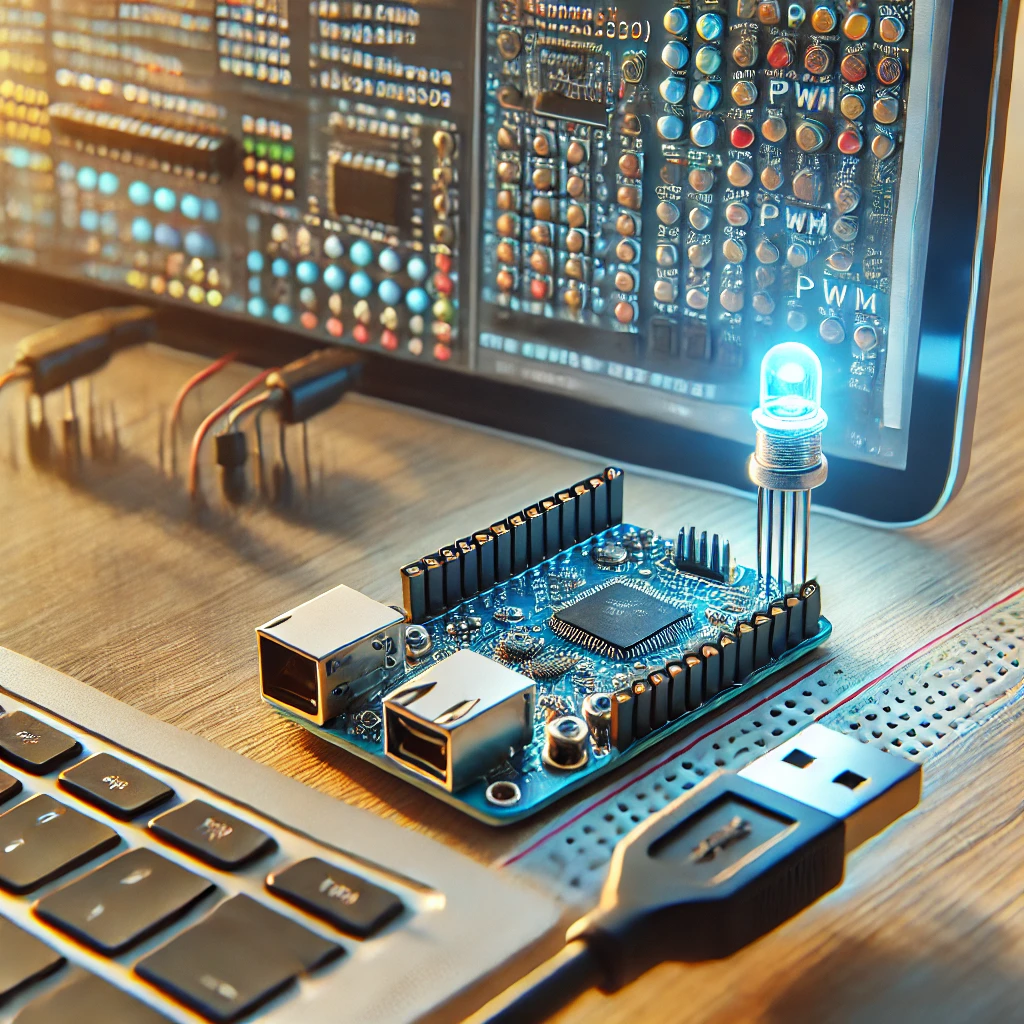
Pulse Width Modulation (PWM) is a powerful method for controlling electronic devices by varying the width of a digital pulse to simulate an analog output. PWM is commonly used in a variety of applications, including motor control, LED dimming, and even audio signal generation. The ESP32 microcontroller, which boasts dual-core processing, built-in Wi-Fi, and Bluetooth capabilities, offers a flexible and efficient way to generate PWM signals, making it an excellent choice for embedded systems projects.
While the ESP32 doesn’t have true analog output pins, it is equipped with the ability to simulate analog signals via PWM on nearly all of its GPIO pins. By leveraging the Arduino IDE, developers can easily program the ESP32 to generate PWM signals and control devices that require analog-like output. This guide will walk you through the concepts of PWM, setting up the Arduino IDE for the ESP32, and understanding how to use PWM on the ESP32 for practical applications.
Understanding PWM (Pulse Width Modulation)
PWM is a technique used to generate a modulated signal that mimics an analog output. Despite being a digital signal, PWM allows us to adjust the average voltage output by changing the width of the pulse.
-
What is PWM? Pulse Width Modulation is a method of controlling the amount of power delivered to an electronic device by adjusting the duration of time a signal stays “on” during each cycle. A typical PWM signal has two primary states: high (on) and low (off). By adjusting the proportion of time the signal is high, you can control the amount of energy supplied to a device.
-
How PWM Works: A PWM signal consists of a series of pulses with a fixed frequency. The duty cycle of the signal determines the percentage of time the signal remains high during one complete cycle. For instance, a 50% duty cycle means the signal stays on for half the time and off for the other half, which effectively reduces the average voltage seen by the device.
-
The Components of PWM:
- Duty Cycle: The percentage of time the signal is high (on). A higher duty cycle means a higher average output voltage. A 100% duty cycle means the signal is continuously high, while a 0% duty cycle means the signal is always low.
- Frequency: The rate at which the signal completes one full cycle (on + off). The higher the frequency, the smoother the signal, making it more suitable for applications like motor control.
- Period: The total time it takes for the signal to complete one cycle. The period is inversely proportional to the frequency. For example, a 1kHz frequency has a period of 1 millisecond (1ms).
-
Real-World Applications: PWM has widespread use across various fields. Common applications include:
- Motor Control: PWM is used to control the speed of motors. By adjusting the duty cycle, you can regulate the average power supplied to the motor, effectively controlling its speed.
- LED Dimming: PWM is also used to control the brightness of LEDs. By adjusting the duty cycle, the perceived brightness can be varied, as the LED turns on and off at high speed, with the average brightness depending on the duty cycle.
- Audio Synthesis: In audio applications, PWM can generate different audio tones by varying the frequency and duty cycle.
-
Why Use PWM? PWM is advantageous because it allows precise control of analog devices using only digital signals. Digital signals are easier to generate and are more robust in noisy environments, making PWM a reliable choice for controlling analog devices.
-
PWM Frequency and Its Effects: The frequency of a PWM signal is important because it determines how smooth the output will be. High-frequency PWM is ideal for applications like LED dimming, as it avoids flickering. For motors, lower frequencies are typically used, as they reduce power loss and heat generation in the motor.
Introduction to the ESP32
The ESP32 is a highly capable microcontroller from Espressif Systems. It offers a range of advanced features, such as dual-core processing, Bluetooth, Wi-Fi, and a large number of GPIO pins, making it an ideal choice for various IoT and embedded systems applications. One of the standout features of the ESP32 is its ability to generate PWM signals on almost all of its GPIO pins.
-
ESP32 Overview: The ESP32 is a 32-bit microcontroller with a dual-core processor running at up to 240 MHz. It supports various communication protocols like I2C, SPI, UART, and more, making it an excellent choice for applications requiring connectivity and real-time processing.
-
PWM Capabilities of the ESP32: Unlike older microcontrollers that support PWM on only a few pins, the ESP32 can output PWM signals on most of its GPIO pins. This gives developers flexibility in designing circuits and connecting multiple devices without worrying about limited PWM pins.
-
Why Choose the ESP32 for PWM Projects? The ESP32’s hardware supports high-resolution PWM, with up to 16-bit precision. Additionally, the microcontroller features multiple independent timers, allowing for fine-grained control over PWM frequencies and duty cycles for different channels.
-
GPIO Pins and PWM Output: While most of the ESP32 GPIO pins support PWM, there are a few considerations. Some pins, such as GPIOs 34-39, are input-only, and others may conflict with specific hardware functions (e.g., Flash, SPI). It is important to check the ESP32 datasheet for detailed information on which pins are best suited for PWM output.
-
Advantages Over Other Microcontrollers: The ESP32 offers significant advantages over older microcontrollers like the Arduino Uno. With more processing power, memory, and GPIO flexibility, the ESP32 can handle more complex PWM tasks and is suitable for a wider range of applications, including IoT projects, robotics, and automation.
-
Internal Hardware Support: The ESP32 features multiple timers that can generate PWM signals independently of the main CPU, making it highly efficient for real-time applications. These timers are crucial in generating high-frequency PWM signals without affecting the performance of other tasks.
-
Real-World Use Cases of the ESP32: Some common use cases for the ESP32 include controlling the brightness of LED strips, adjusting the speed of motors in robotics, and even generating audio signals for sound synthesis.
Setting Up the Arduino IDE for ESP32
To use the ESP32 with the Arduino IDE, you first need to install the necessary board package and configure the IDE. The Arduino IDE is a user-friendly development environment that simplifies programming and uploading code to microcontrollers.
-
Installing the Arduino IDE: Download and install the Arduino IDE from the official Arduino website. The IDE is available for Windows, macOS, and Linux.
-
Setting Up ESP32 in the Arduino IDE: After installing the IDE, you need to install the ESP32 board package. Go to File > Preferences and enter the following URL in the “Additional Boards Manager URLs” field:
-
Installing the ESP32 Package: Once the URL is added, go to Tools > Board > Board Manager and search for “ESP32”. Click the “Install” button next to the ESP32 by Espressif Systems package to install the necessary files.
-
Selecting the ESP32 Board: Once the ESP32 package is installed, go to Tools > Board and select the appropriate ESP32 board. The ESP32 Dev Module is a good choice for most users.
-
Connecting the ESP32 to Your Computer: Use a micro-USB cable to connect the ESP32 to your computer. Ensure that the correct Port is selected under Tools > Port.
-
Uploading a Test Sketch: To verify the setup, upload a simple “Blink” sketch to the ESP32. This will help confirm that the board is correctly configured and the IDE is able to communicate with the ESP32.
-
Troubleshooting Setup Issues: If you encounter issues during setup, ensure that:
- The correct board and port are selected.
- The ESP32 drivers are installed.
- Try using a different USB cable or port if the ESP32 is not recognized.
How PWM Works on the ESP32
The ESP32 allows you to generate PWM signals using its internal timers and GPIO pins. Understanding how to configure and use these features is key to effectively utilizing PWM on the ESP32.
-
PWM Pins on the ESP32: Most GPIO pins on the ESP32 support PWM output. However, it is important to check the ESP32 datasheet for pin limitations. For example, GPIOs 0 to 15 are frequently used for PWM control, but other pins might conflict with other peripheral functions.
-
PWM Channels: The ESP32 supports up to 16 independent PWM channels. This means you can control up to 16 different PWM outputs simultaneously, each with its own frequency and duty cycle. This feature is essential for complex projects requiring control of multiple devices.
-
PWM Frequency: The default PWM frequency on the ESP32 is 1 kHz, but it can be easily modified using the
ledcSetup()function. You can adjust the frequency to suit the needs of your project, whether it’s controlling motors or LEDs. -
Setting PWM Resolution: PWM resolution refers to the number of bits used to define the duty cycle. The ESP32 supports up to 16-bit resolution, allowing for precise control over the duty cycle. Higher resolution results in finer control over the output signal.
-
Configuring PWM Using Arduino Code: The ESP32 PWM functions are controlled using a combination of three main functions:
ledcSetup(channel, freq, resolution): Configures the PWM channel with a specific frequency and resolution.ledcAttachPin(pin, channel): Attaches a PWM channel to a specific GPIO pin.ledcWrite(channel, dutyCycle): Sets the duty cycle for a specific PWM channel.
-
Code Example: Here’s a simple example of how to set up PWM on the ESP32 using the Arduino IDE:
-
Adjusting Duty Cycle: The
ledcWrite()function allows you to adjust the duty cycle of the PWM signal. By changing the value passed toledcWrite(), you can control the intensity of an LED, the speed of a motor, or the power supplied to other devices.
Advanced PWM Control and Applications
Once you have mastered basic PWM control, you can explore advanced features like controlling multiple devices, adjusting frequencies, and using PWM in real-time applications.
-
Multiple PWM Channels: The ESP32’s ability to control up to 16 independent PWM channels means you can control multiple devices simultaneously. For example, you could control the speed of two motors and the brightness of an LED strip independently.
-
Adjusting PWM Frequency: The PWM frequency can be adjusted to suit specific requirements. For example, motors generally operate better at lower frequencies (e.g., 1 kHz), while LEDs require high-frequency PWM to avoid flickering (e.g., 10 kHz or more).
-
Using PWM for Motor Control: PWM is commonly used to control the speed of motors. By adjusting the duty cycle, you can change the average voltage supplied to the motor, effectively controlling its speed.
-
Applications in Robotics: PWM is a critical part of robotics, allowing precise control of motors, sensors, and other components. By using PWM to control motors, robots can navigate, adjust speed, and perform tasks based on real-time sensor input.
Mastering PWM on the ESP32 with the Arduino IDE opens up a world of possibilities for controlling devices in embedded systems projects. From LED dimming and motor control to advanced applications in robotics and IoT, PWM provides an efficient and flexible method for simulating analog output. By understanding how to configure PWM on the ESP32 and leveraging its powerful features, developers can create highly responsive and efficient systems.
By experimenting with various PWM settings, frequencies, and duty cycles, you can unlock the full potential of the ESP32 for a wide range of applications. The combination of the Arduino IDE’s ease of use and the ESP32’s capabilities provides a powerful platform for both beginners and advanced developers alike.
Feel free to check out our other website at http://master3dp.com/ where you can learn to 3D print anything needed for a project.


