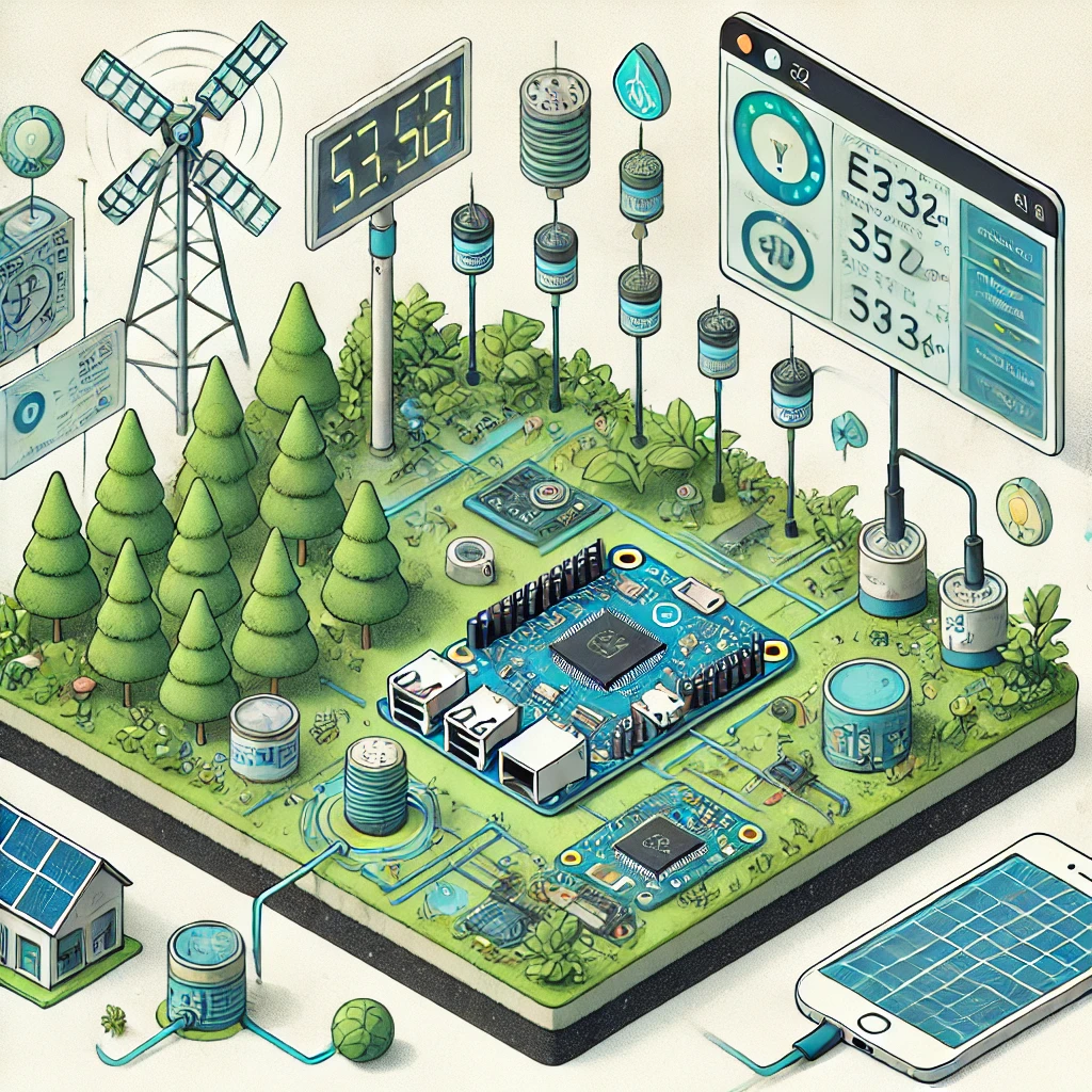
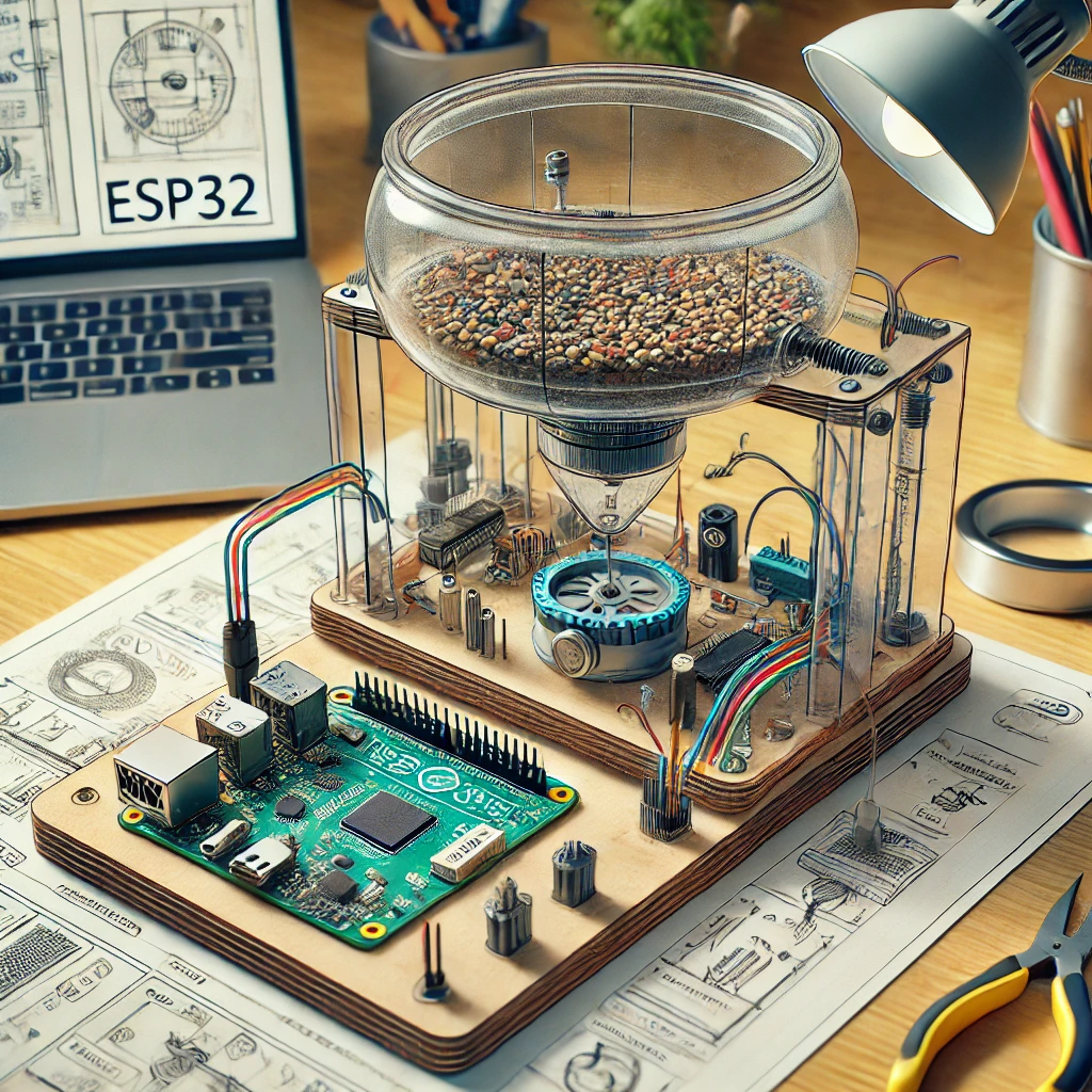
Learn how to turn your ESP32 into an environmental monitoring system, track temperature, humidity, air quality, and more with real-time data and cloud integration.
Monitoring the environment has become a crucial part of addressing global issues like air pollution, climate change, and resource management. While professional environmental monitoring equipment can be expensive, the rise of affordable IoT devices has made it easier for individuals to build cost-effective systems. These DIY projects not only promote awareness but also empower people to contribute to environmental protection.
The ESP32 microcontroller is an excellent tool for creating such systems. Known for its versatility, Wi-Fi connectivity, and low cost, the ESP32 allows seamless integration with a variety of sensors. Whether you’re tracking indoor air quality or monitoring outdoor conditions, this microcontroller can handle it all. This project is ideal for students, hobbyists, and even professionals who need a customizable solution.
In this guide, we’ll walk you through building an environmental monitoring system using ESP32. This project will measure critical parameters like temperature, humidity, air quality, and light intensity. You’ll learn how to set up hardware, write and upload code, test the system, and interpret the data.
The project uses easy-to-find components, and the steps are designed with beginners in mind. Even if you have no prior experience with IoT devices, this guide will help you succeed. The finished product is a portable, scalable, and powerful tool that can be used for various applications, including education, research, and daily environmental tracking.
By the end of this article, you’ll not only have a functional monitoring system but also a deeper understanding of how IoT technology can aid environmental conservation. Let’s start by understanding what you’ll need for this project.
Required Components
To build the ESP32 Environmental Monitoring System, you need specific components. Ensuring you have the correct parts beforehand saves time and avoids mid-project interruptions. Below is a detailed list of the components required:
- ESP32 Development Board
The ESP32 board acts as the system’s brain, collecting data from sensors and transmitting it to displays or cloud services. Its dual-core processor ensures it can handle multiple tasks, making it ideal for environmental monitoring. - DHT22 Temperature and Humidity Sensor
This sensor provides accurate measurements of temperature and humidity. It’s better than its predecessor, the DHT11, offering a wider range and higher precision. These parameters are crucial for understanding the environment. - MQ-135 Gas Sensor
The MQ-135 is a versatile gas sensor that can detect harmful gases like CO2, ammonia, and benzene. It’s widely used for air quality monitoring and is essential for assessing pollution levels. - BH1750 Light Intensity Sensor
This I2C-based sensor measures ambient light with high precision. It’s useful for applications where light levels are important, such as monitoring plant growth or indoor lighting conditions. - Power Supply
Use either a USB power adapter for stationary setups or a rechargeable LiPo battery for portable systems. Consider a solar-powered solution for outdoor use. - Jumper Wires and Breadboard
These are essential for connecting your sensors and peripherals to the ESP32. They allow you to test the circuit before making it permanent. - Optional Components
Additional items like an LCD display or a weatherproof enclosure can enhance your project. A display shows real-time data locally, while an enclosure protects the system in outdoor settings.
Each component serves a critical function, and selecting the right parts ensures the system performs reliably. Now that we have the components ready, let’s move on to assembling the hardware.
Setting Up the Hardware
Step 1: Connecting the Sensors
The first step in building your system is to connect the sensors to the ESP32. Begin by wiring each sensor individually:
- DHT22 Temperature and Humidity Sensor
- Connect the DHT22’s data pin to GPIO4 on the ESP32.
- Attach the VCC and GND pins to the 3.3V and ground pins, respectively.
- Use a pull-up resistor (4.7k to 10k ohms) between the data pin and VCC for stable readings.
- MQ-135 Gas Sensor
- Plug the analog output pin of the MQ-135 into GPIO36 (A0) on the ESP32.
- Power the sensor using the 5V and GND pins of the ESP32.
- Ensure proper ventilation around the sensor for accurate readings.
- BH1750 Light Intensity Sensor
- Connect the SDA and SCL pins to GPIO21 and GPIO22 for I2C communication.
- Power the sensor by connecting its VCC and GND pins to the ESP32’s power and ground pins.
- Keep the sensor away from direct sunlight to prevent saturation.
Step 2: Testing the Connections
Once all sensors are connected, verify each connection on a breadboard. Use a multimeter to ensure proper power delivery and check for loose wires. Testing the setup early helps avoid debugging issues later.
Step 3: Assembling the Circuit
For a portable or permanent setup, solder the components onto a prototyping board. Use heat shrink tubing or electrical tape to insulate exposed wires. This step ensures the circuit is durable and compact for long-term use.
Writing and Uploading the Code
Step 1: Install Required Libraries
Programming the ESP32 requires specific libraries. Download and install the following using the Arduino IDE:
- DHT Library for temperature and humidity data.
- Adafruit_BH1750 Library for light intensity measurements.
- MQ135 Library for air quality monitoring.
Ensure your Arduino IDE is configured to work with ESP32 boards.
Step 2: Writing the Code
Develop a script to collect data from all sensors and display it on the Serial Monitor or an LCD display. The following code initializes the sensors and reads data:
Step 3: Uploading the Code
Uploading the code to the ESP32 is a critical step in making your environmental monitoring system operational. Follow these detailed instructions to ensure a smooth setup process:
1. Connect the ESP32 to Your Computer
- Use a USB cable to connect the ESP32 to your computer. Ensure the cable supports data transfer and is not a charge-only cable.
- Verify the connection by observing the onboard LED on the ESP32; it should light up, indicating power.
2. Open the Arduino IDE
- Launch the Arduino IDE on your computer. If you haven’t installed it yet, download it from the official Arduino website and follow the installation instructions.
- Ensure the ESP32 board package is installed. If not, follow these steps:
- Open File > Preferences.
- Paste the ESP32 board URL:
https://dl.espressif.com/dl/package_esp32_index.jsoninto the Additional Board Manager URLs field. - Go to Tools > Board > Boards Manager, search for “ESP32,” and click Install.
3. Select the Correct Board and Port
- Go to Tools > Board > ESP32 Arduino > (Your ESP32 Model) and select the specific ESP32 board you’re using (e.g., “ESP32 Dev Module”).
- Under Tools > Port, select the COM port to which your ESP32 is connected. If you’re unsure, unplug and replug the ESP32 to see which port appears.
4. Open or Write the Code
- Open the prewritten code for your project in the Arduino IDE or write your own. Ensure the code includes the necessary libraries for your sensors and any Wi-Fi credentials for cloud logging.
- For example, if you’re using a DHT11 sensor, include:
- Replace placeholders such as
WiFi_SSIDandWiFi_PASSWORDwith your actual Wi-Fi credentials.
5. Verify the Code
- Click the Checkmark (Verify) icon in the Arduino IDE toolbar. This step compiles the code and checks for any errors.
- Fix any issues or typos highlighted during the verification process before proceeding.
6. Upload the Code
- Once verified, click the Arrow (Upload) icon in the toolbar.
- Monitor the bottom window of the Arduino IDE for the progress bar and messages.
- The message “Done uploading” indicates a successful upload.
- If an error occurs, ensure the correct COM port and board are selected, and press the BOOT button on the ESP32 during the upload process.
7. Open the Serial Monitor
- Navigate to Tools > Serial Monitor to open the Serial Monitor.
- Set the baud rate to match the one defined in your code, typically
115200. - Observe the real-time data output from the sensors. This will include readings such as temperature, humidity, air quality, and light intensity.
8. Debugging Common Issues
- No Output on Serial Monitor:
- Ensure the correct baud rate is selected.
- Check that the sensors are properly connected to the correct GPIO pins.
- Upload Errors:
- Press and hold the BOOT button on the ESP32 until the upload process begins.
9. Fine-Tune the Code (Optional)
- Review the sensor outputs for accuracy. If values seem off, adjust calibration parameters in the code. For example:
- For the MQ-135 air quality sensor, ensure it has a warm-up period of at least 24 hours for reliable readings.
Step 4: Assembling the Monitoring Hardware
Now that your ESP32 has the necessary code uploaded, it is time to integrate the sensors, display, and other hardware components into a cohesive setup.
1. Attach the Sensors to the Breadboard
- Place your sensors, such as the DHT11 or MQ-135, onto the breadboard.
- Connect the VCC pin of each sensor to the 3.3V pin of the ESP32 using jumper wires.
- Connect the GND pin of each sensor to the ground (GND) pin on the ESP32.
- Attach the sensor data pins to designated GPIO pins on the ESP32 as specified in your code. For example:
- DHT11: GPIO4
- MQ-135: GPIO34
- Use the breadboard to organize connections, ensuring no wires overlap or interfere with one another.
2. Integrate the Display Module
- If using an OLED or LCD display, connect its SCL (Serial Clock Line) and SDA (Serial Data Line) pins to the appropriate GPIO pins on the ESP32.
- Reference the display module’s datasheet to ensure correct pin mapping.
- Secure the display onto your project enclosure or mounting surface, ensuring visibility.
3. Add Additional Modules (Optional)
- If you’re using a real-time clock (RTC) module, connect it to the ESP32 following the same procedure for VCC, GND, SCL, and SDA pins.
- For GPS or GSM modules, integrate these by connecting their UART pins to the ESP32’s RX and TX pins.
4. Secure Connections
- Once all components are in place, double-check the connections.
- Use zip ties, shrink tubing, or hot glue to secure wires and components. This minimizes the risk of disconnection or short circuits during operation.
5. Power Supply
- Power the ESP32 using a rechargeable battery pack for portability or connect it directly to a power source via USB.
- If using a solar panel, connect it to a charge controller linked to the battery for continuous power supply.
6. Enclose the Hardware
- Place the assembled setup inside a waterproof and heat-resistant enclosure for outdoor use.
- Cut holes for the display and sensors to ensure accurate data readings and ease of viewing.
- Use screws or adhesive to secure the enclosure components.
7. Test the Setup
- Power on the system and observe the display or Serial Monitor output to confirm that all sensors and components are functioning as expected.
- Walk around with the setup to simulate real-world conditions and verify sensor accuracy.
Step 5: Setting Up Data Logging and Visualization
To make your environmental monitoring system truly impactful, it is essential to record and visualize the data it collects. This allows you to analyze trends and identify patterns over time.
1. Choose a Cloud Platform
- Decide on a cloud service such as ThingSpeak, Adafruit IO, or Blynk. These platforms offer free and paid options for data logging and visualization.
2. Configure Wi-Fi on the ESP32
- In the Arduino code, enter your Wi-Fi SSID and password to allow the ESP32 to connect to your local network. For example:
- Re-upload the modified code to the ESP32 and confirm a successful connection via the Serial Monitor.
3. Send Data to the Cloud
- Use the platform’s API to transmit sensor readings. For instance, with ThingSpeak:
- Ensure the API key and field mapping match the platform settings.
4. Create Dashboards
- Log into your cloud account and configure widgets such as line charts, bar graphs, and gauges to visualize the sensor data.
- Set up email or SMS alerts for specific conditions, like poor air quality or high temperatures.
5. Test the Data Flow
- Simulate changes in environmental conditions, like blowing warm air onto the DHT11 or exposing the MQ-135 to various chemicals.
- Confirm that the data updates on the cloud platform in real-time.
6. Offline Data Logging (Optional)
- Integrate an SD card module with the ESP32 for local storage. Write sensor data to the card using the
SDlibrary in Arduino. - Periodically transfer this data to a computer for offline analysis.
Step 6: Maintenance and Calibration
To ensure long-term performance and accuracy, your monitoring system requires periodic maintenance and calibration.
1. Clean the Sensors
- Dust and debris can affect sensor readings. Gently clean the sensors using a soft brush or compressed air.
2. Recalibrate Sensors
- For sensors like the MQ-135, recalibrate them periodically by placing them in a controlled environment with known air quality parameters.
3. Update the Code
- As new libraries or improvements become available, update your code to take advantage of bug fixes and additional features.
4. Check Connections
- Inspect the wiring and ensure all connections remain secure, especially in outdoor setups exposed to temperature changes.
5. Monitor Power Supply
- Recharge or replace the battery as needed. For solar-powered setups, clean the panel to maintain efficiency.
6. Analyze Data Trends
- Periodically review your cloud dashboard to identify patterns, such as seasonal variations in air quality or temperature.
By following these steps, you can maintain a reliable and accurate environmental monitoring system capable of tracking changes in your surroundings over time.
1. What is the ESP32, and why is it suitable for environmental monitoring?
The ESP32 is a low-cost, powerful microcontroller with built-in Wi-Fi and Bluetooth capabilities, making it ideal for IoT projects like environmental monitoring. It can interface with various sensors to collect data and transmit it to cloud platforms for visualization.
2. Can this setup be used outdoors?
Yes, this setup can be used outdoors. To ensure durability, place the components in a waterproof, heat-resistant enclosure. Proper sealing of sensor and display openings is essential to protect against environmental factors like rain and dust.
3. Do I need programming experience to complete this project?
Basic programming skills in Python or Arduino IDE are helpful but not mandatory. Detailed guides and pre-written codes are available to assist beginners in setting up the system successfully.
4. What kind of data can I monitor using this system?
You can monitor temperature, humidity, air quality (e.g., CO2 levels), light intensity, soil moisture, and more. The types of data depend on the sensors you choose to integrate with your ESP32.
5. How can I view the collected data?
You can view real-time data on an OLED or LCD display connected to the ESP32. Additionally, the system can send data to cloud platforms for logging and visualization, such as:
6. How can I extend the battery life for this project?
To extend battery life, use energy-efficient components, enable deep-sleep mode on the ESP32, and integrate a solar panel to recharge the battery automatically. This approach ensures continuous operation with minimal intervention.
7. Can I add more sensors in the future?
Yes, the ESP32 is versatile and supports a wide range of sensors. You can expand the system by adding more sensors as long as the GPIO pins and power supply can accommodate them.
8. What are some troubleshooting tips if the system doesn’t work?
- Check all connections for loose or misplaced wires.
- Verify that the sensors are receiving power and connected to the correct GPIO pins.
- Use the Serial Monitor in Arduino IDE to debug errors in the code or sensor readings.
- Ensure the ESP32 is connected to Wi-Fi if using cloud platforms like www.randomnerdtutorials.com.
9. Is it possible to integrate other IoT devices with this system?
Yes, the ESP32 supports multiple communication protocols like MQTT and HTTP, allowing you to integrate smart devices, such as smart lights or alarms, for automated responses based on environmental data.
10. Can this system help in monitoring environmental compliance for industries?
Absolutely. With additional sensors and logging features, the system can track air and water quality, ensuring compliance with environmental regulations. Data can be exported for analysis or reporting purposes.
Did you find this helpful? If you did, please share and stay tuned to our blog !!
Feel free to visit master3dp.com for all your 3d printing know-how!!

